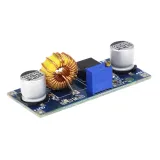
SKU: OT2004-A113 Número de artículo: AA270 EAN: 8179262862427

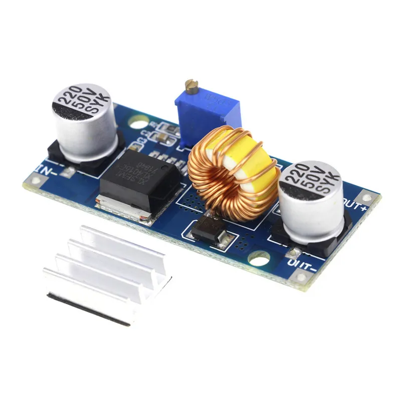
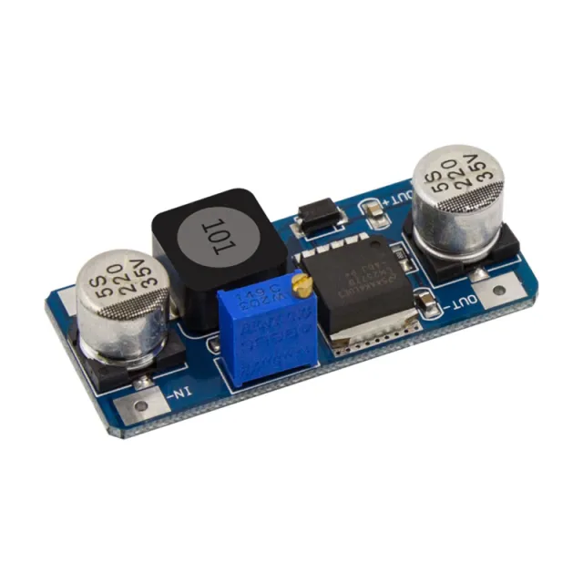
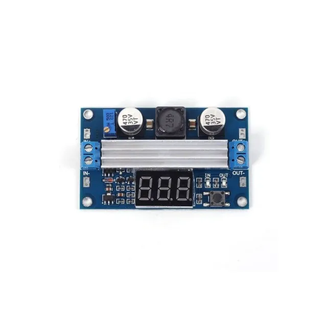
Voltaje de entrada 4-38VDC
Voltaje de salida 1.25-36VDC, regulable
Potencia de salida 0-5A, con protección contra cortocircuito en la salida.
Salida máxima 75W con protección térmica
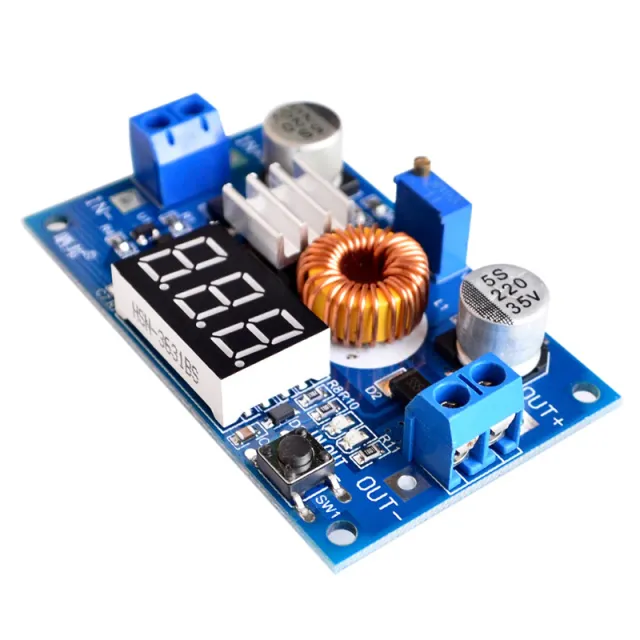
Incluye disipador de calor que se suministra sin montar. Puede fijarse mediante la tira 3M adjunta.
Dimensiones
Longitud: 5,4cm
Anchura: 2,45cm
Altura: 1,7cm
Así conectas el Módulo step-down regulable 4~38V 5A 96% alta eficiencia XL4015 a un Arduino UNO o ESP32, con un sketch de ejemplo que puedes subir directamente.
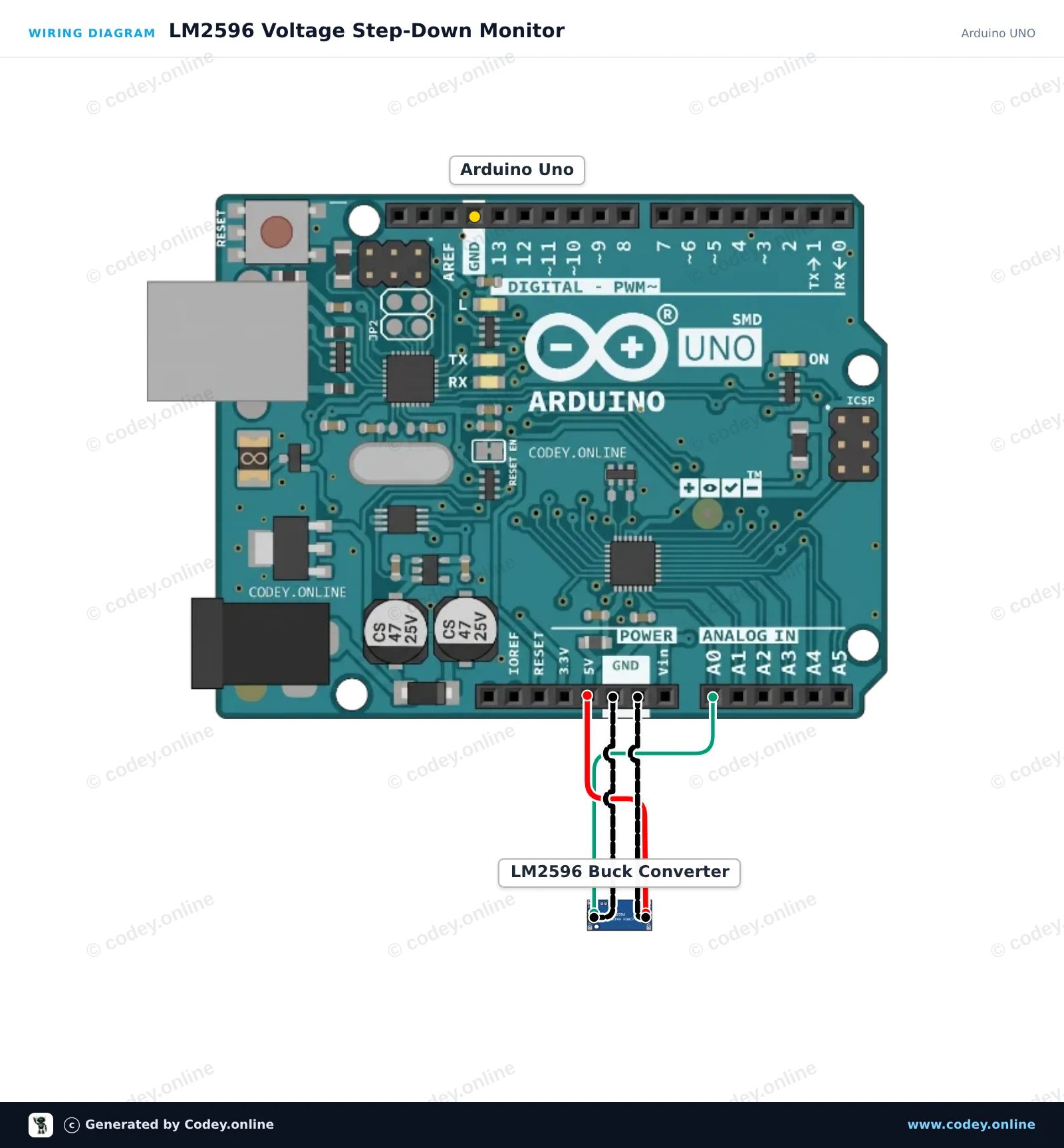
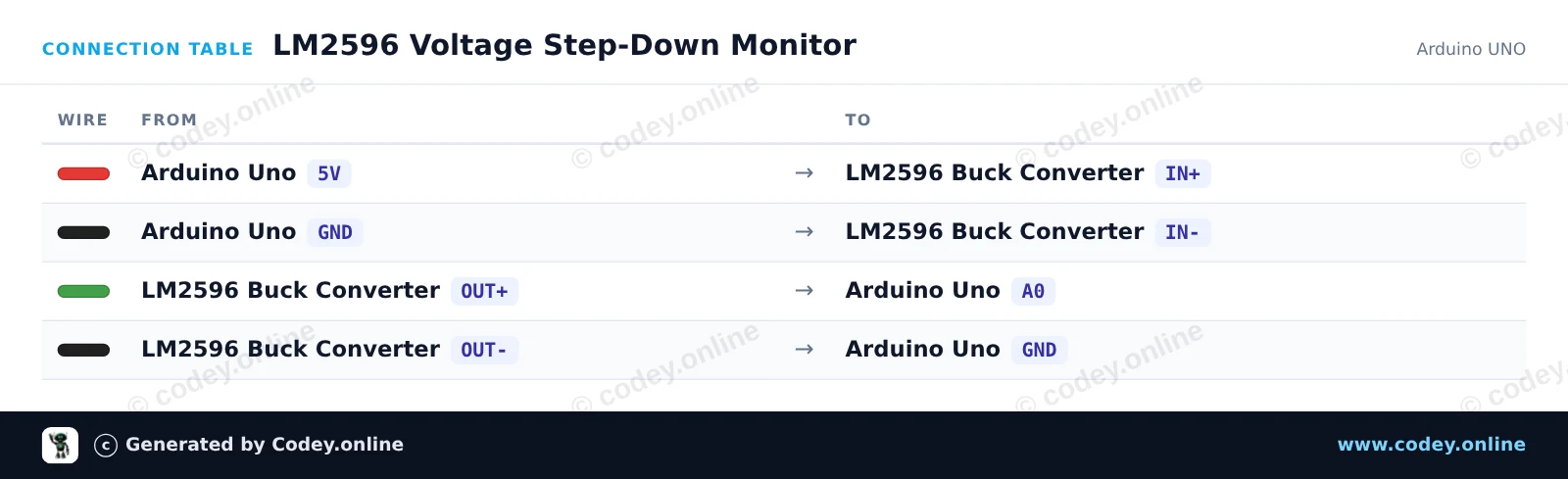
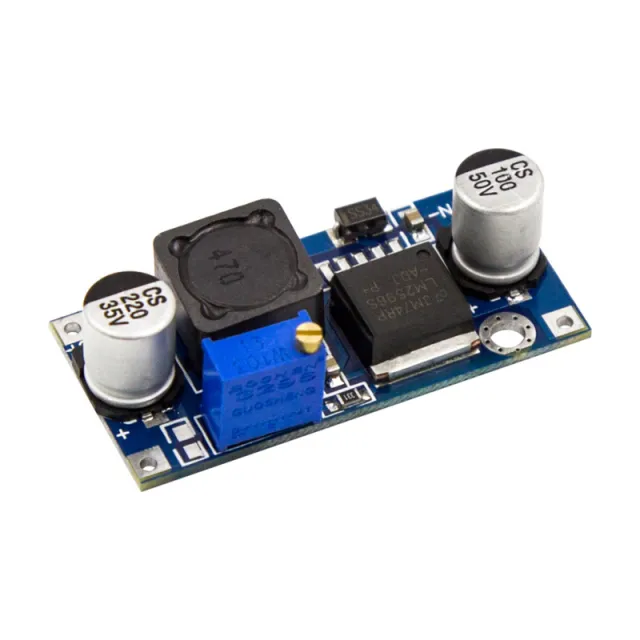
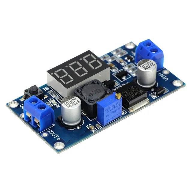
Este proyecto alimenta el módulo step-down LM2596 desde la línea de 5V del Arduino y mide su tensión de salida regulada en el pin analógico A0. Ajusta el potenciómetro integrado con un pequeño destornillador para observar los cambios de voltaje en tiempo real que se muestran en el Serial Monitor (mantén la salida por debajo de 5V).
/*
 * ==================================================================
 *  Generated by Codey.online  —  https://www.codey.online
 * ==================================================================
 *  Project   : LM2596 Voltage Step-Down Monitor
 *  Board     : Arduino UNO (arduino:avr:uno)
 *  Parts     : Adjustable Step-down Module 3-40VDC 1.5-35VDC LM2596
 *  Libraries : none (built-in)
 *
 *  Codey Online is an AI-powered browser IDE for Arduino and ESP32.
 *  Describe your project and Codey writes the code, draws the wiring
 *  diagram and uploads it to your board, straight from the browser.
 *  This code is free to use, modify and share, without warranty.
 * ==================================================================
 */

const int voltagePin = A0;

void setup() {
  Serial.begin(115200);
  while (!Serial) {
    ; // Wait for serial port to connect
  }
  Serial.println(F("LM2596 Step-Down Voltage Monitor"));
  Serial.println(F("Turn the onboard trimmer to adjust the output voltage (0-5V)."));
}

void loop() {
  int rawValue = analogRead(voltagePin);
  float voltage = rawValue * (5.0 / 1023.0);

  Serial.print(F("ADC Value: "));
  Serial.print(rawValue);
  Serial.print(F(" | Output Voltage: "));
  Serial.print(voltage, 2);
  Serial.println(F(" V"));

  delay(500);
}Wiring diagram and example code generated by Codey.online — https://www.codey.online
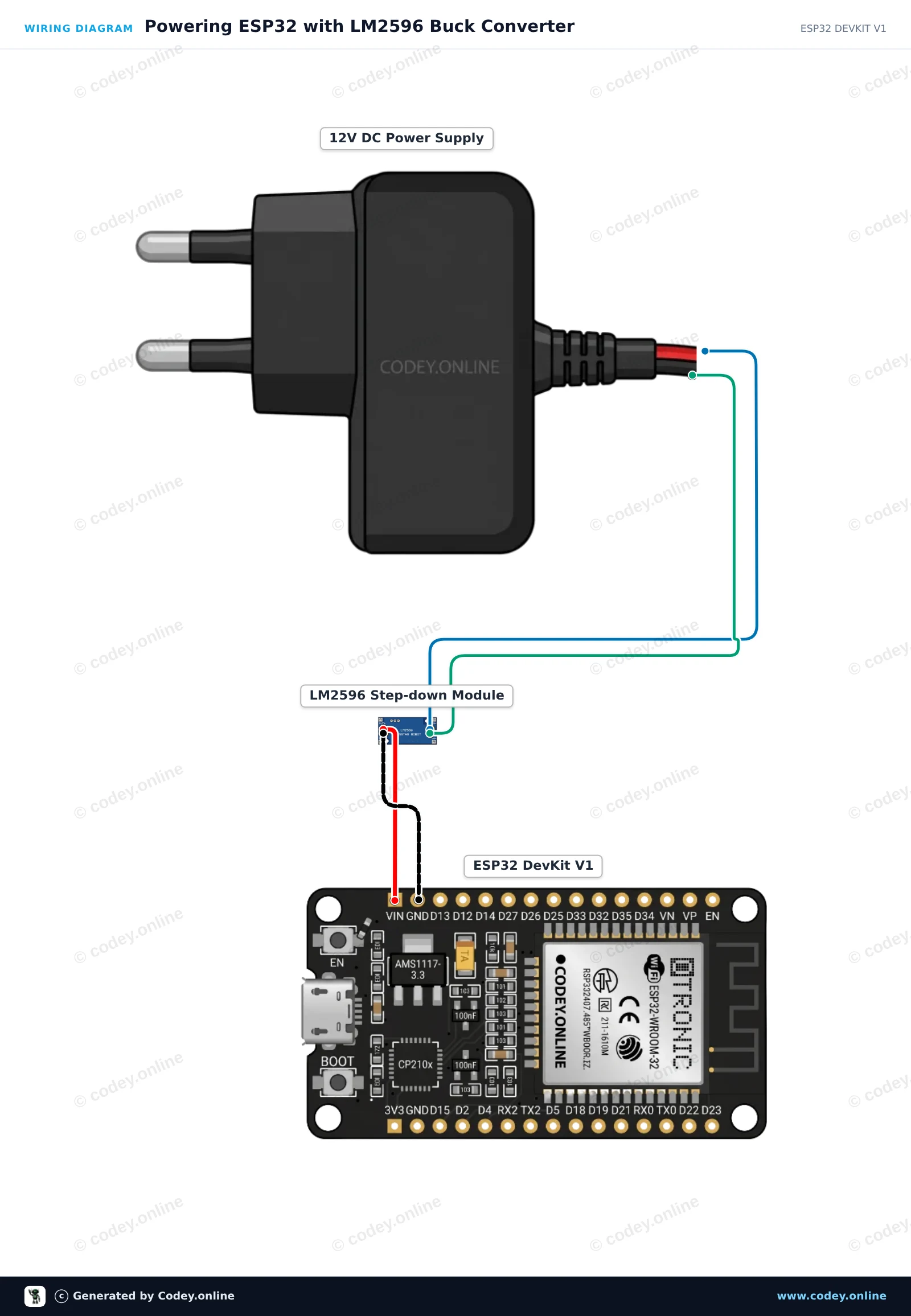
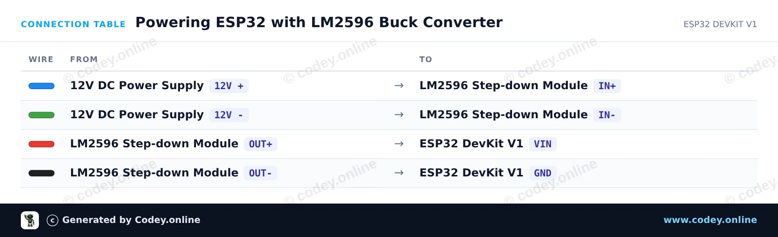
Antes de conectar el ESP32, usa un multímetro para ajustar el potenciómetro trimmer del LM2596 hasta que OUT+ marque exactamente 5.0V. El módulo reduce de forma eficiente la entrada de 12V a una salida estable de 5V para alimentar el ESP32 a través de VIN y GND. Cuando se conecta, el ESP32 arranca, parpadea su LED de estado integrado y envía mensajes heartbeat por Serial.
/*
 * ==================================================================
 *  Generated by Codey.online  —  https://www.codey.online
 * ==================================================================
 *  Project   : Powering ESP32 with LM2596 Buck Converter
 *  Board     : ESP32 DEVKIT V1 (esp32:esp32:esp32doit-devkit-v1)
 *  Parts     : Adjustable Step-down Module 3-40VDC 1.5-35VDC LM2596
 *  Libraries : none (built-in)
 *
 *  Codey Online is an AI-powered browser IDE for Arduino and ESP32.
 *  Describe your project and Codey writes the code, draws the wiring
 *  diagram and uploads it to your board, straight from the browser.
 *  This code is free to use, modify and share, without warranty.
 * ==================================================================
 */

// LM2596 Step-Down Buck Converter ESP32 Power Demo
// Note: Always adjust LM2596 output to 5V before connecting to VIN!

const int LED_PIN = 2; // Onboard LED

void setup() {
  Serial.begin(115200);
  pinMode(LED_PIN, OUTPUT);

  Serial.println("LM2596 Step-Down Buck Converter Demo");
  Serial.println("ESP32 successfully running on regulated 5V power!");
}

void loop() {
  // Turn LED on
  digitalWrite(LED_PIN, HIGH);
  Serial.print("Uptime: ");
  Serial.print(millis() / 1000);
  Serial.println(" s | Power Status: OK (LED ON)");
  delay(500);

  // Turn LED off
  digitalWrite(LED_PIN, LOW);
  delay(500);
}Wiring diagram and example code generated by Codey.online — https://www.codey.online





 English
  Nederlands
  Frans
Frans  Deutsch
  Italiano
  Suomi
Suomi  Polski
  Dansk
Dansk  Ελληνικά
  Български
  Čeština
  Hrvatski
  Svenska
  Aileen