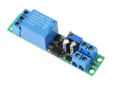
SKU: OT3260 Número de artículo: NA445 EAN: 8720618231529

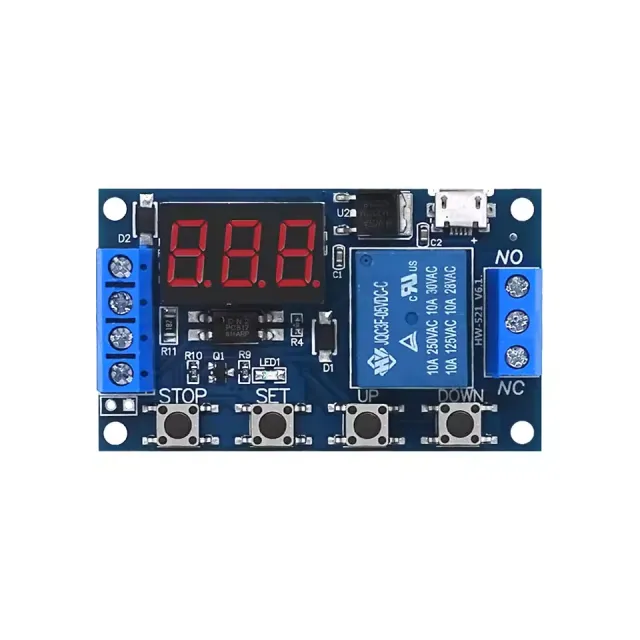
Este módulo de relé con retardo de tiempo funciona a 12V y puede ajustarse mediante la resistencia de tornillo.
Voltaje de trabajo: DC 12V
Consumo de corriente (cuando está activado): ~46mA
Tensión máxima a través del relé: 30VDC o 250VAC
Corriente máxima a través del relé: 10A
Retardo ajustable entre 0.1 y 25 segundos
Para instrucciones y un esquema de conexión tenemos la Guía de inicio rápido OTRONIC para el módulo relé con retardo de tiempo ajustable 12V a su disposición.
Instrucciones:
Este módulo de relé con retardo de tiempo ajustable OTRONIC® tiene un retardo ajustable para la desconexión (caída).
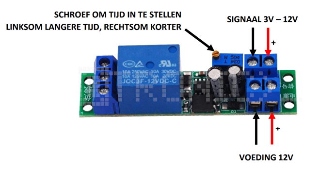
Probar el relé
Puede probar el tiempo configurado del relé sin un control externo.
Conecte una alimentación de 12V a VCC y GND (alimentación). Sin señal, el relé ejecutará una sola vez el
retardo de tiempo. Puede oírlo por el clic del relé.
Utilice la resistencia de tornillo para ajustar el tiempo. Gire a la izquierda para un tiempo más largo y a la derecha
para un tiempo más corto.
ATENCIÓN: Se necesitan varias vueltas de la resistencia para ajustar el tiempo.
Dimensiones
Longitud: 6,68cm
Anchura: 1,6cm
Altura: 1,68cm
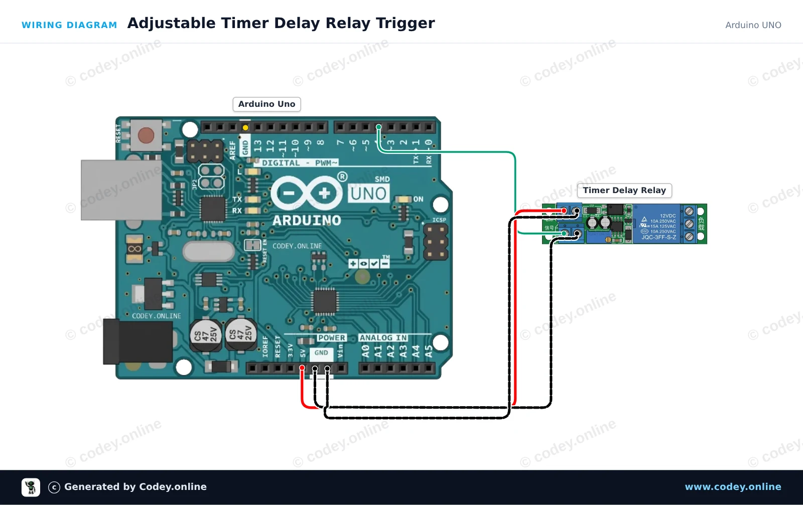
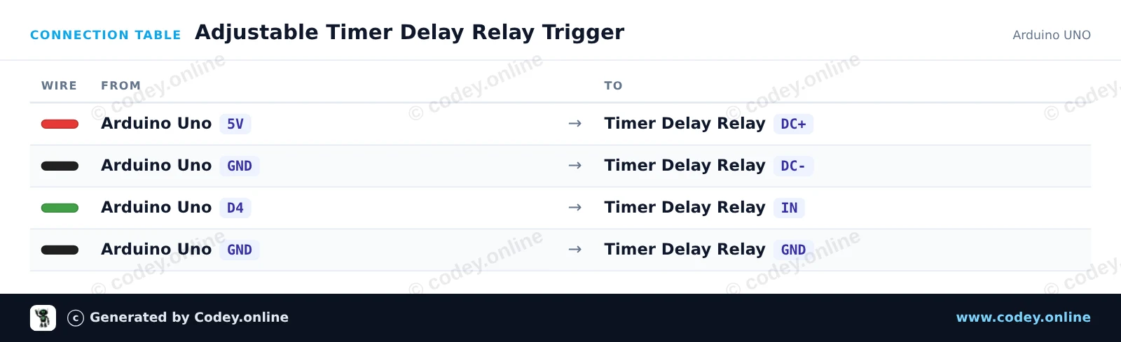
Así conectas el Módulo relé con retardo de tiempo ajustable 12V a un Arduino UNO o ESP32, con un sketch de ejemplo que puedes subir directamente.
Este proyecto muestra cómo activar un módulo de relé con retardo de temporizador ajustable usando un Arduino Uno. El Arduino envía un pulso corto desde el pin digital 4 al pin de activación IN, activando el ciclo de retardo del temporizador integrado. Ajusta el potenciómetro del módulo de relé para cambiar la duración de la activación del relé.
/*
 * ==================================================================
 *  Generated by Codey.online  —  https://www.codey.online
 * ==================================================================
 *  Project   : Adjustable Timer Delay Relay Trigger
 *  Board     : Arduino UNO (arduino:avr:uno)
 *  Parts     : DC 12V adjustable timer delay, time delay relay turn off switch module time relay time switch 0~25sec for smart home, automatic control
 *  Libraries : none (built-in)
 *
 *  Codey Online is an AI-powered browser IDE for Arduino and ESP32.
 *  Describe your project and Codey writes the code, draws the wiring
 *  diagram and uploads it to your board, straight from the browser.
 *  This code is free to use, modify and share, without warranty.
 * ==================================================================
 */

// Timer Delay Relay Module Demo
// Sends a trigger pulse to start the module's countdown delay.

const int triggerPin = 4;

void setup() {
  pinMode(triggerPin, OUTPUT);
  digitalWrite(triggerPin, LOW);

  Serial.begin(115200);
  Serial.println(F("Timer Delay Relay Demo Initialized."));
}

void loop() {
  Serial.println(F("Triggering relay delay cycle..."));

  // Send a 200 ms HIGH pulse to trigger the module
  digitalWrite(triggerPin, HIGH);
  delay(200);
  digitalWrite(triggerPin, LOW);

  Serial.println(F("Trigger sent. Waiting for delay cycle to complete..."));

  // Wait 10 seconds before triggering the next cycle
  delay(10000);
}Wiring diagram and example code generated by Codey.online — https://www.codey.online
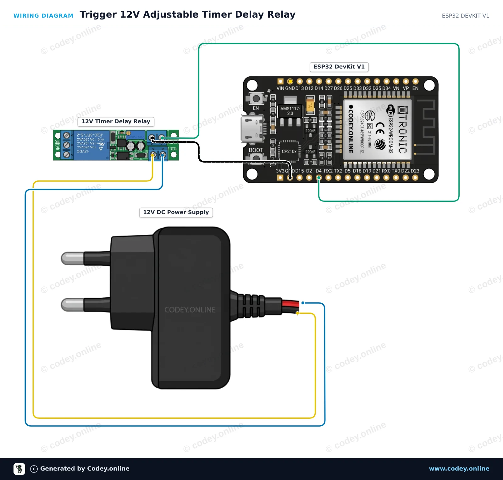
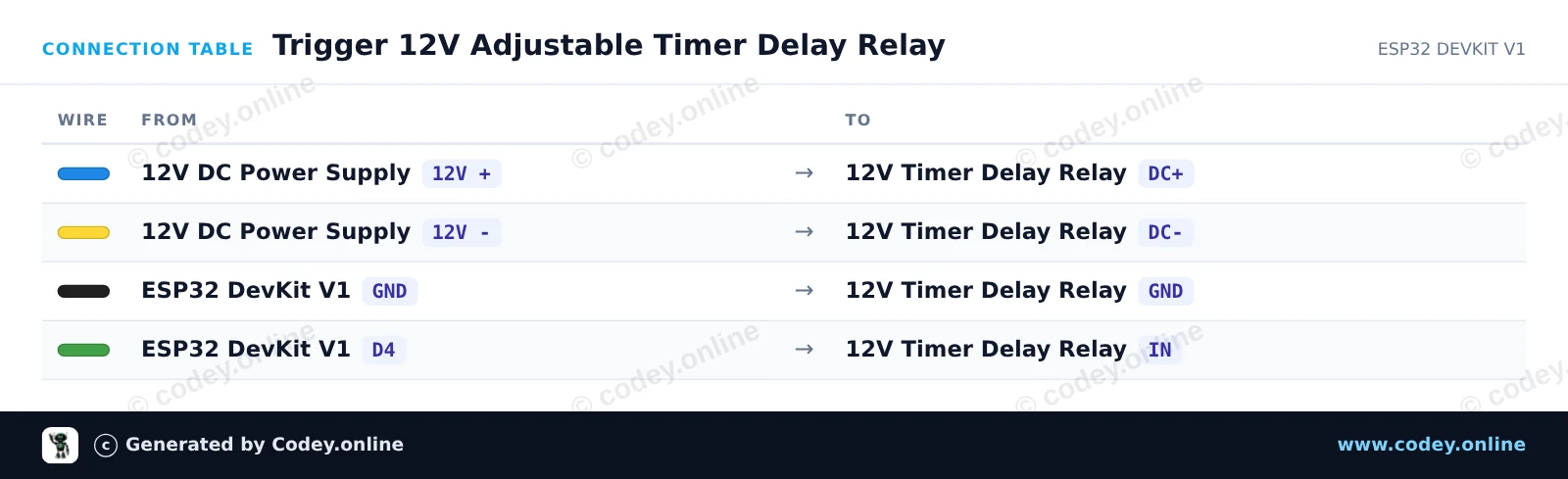
Este proyecto demuestra cómo activar un módulo de relé temporizado ajustable de 12V usando un ESP32. El ESP32 envía un breve pulso de disparo para iniciar la cuenta atrás, y el relé permanece energizado durante el tiempo configurado por el potenciómetro onboard (0 a 25 seconds).
/*
 * ==================================================================
 *  Generated by Codey.online  —  https://www.codey.online
 * ==================================================================
 *  Project   : Trigger 12V Adjustable Timer Delay Relay
 *  Board     : ESP32 DEVKIT V1 (esp32:esp32:esp32doit-devkit-v1)
 *  Parts     : DC 12V adjustable timer delay, time delay relay turn off switch module time relay time switch 0~25sec for smart home, automatic control
 *  Libraries : none (built-in)
 *
 *  Codey Online is an AI-powered browser IDE for Arduino and ESP32.
 *  Describe your project and Codey writes the code, draws the wiring
 *  diagram and uploads it to your board, straight from the browser.
 *  This code is free to use, modify and share, without warranty.
 * ==================================================================
 */

// Pin connected to the IN trigger pin of the timer relay module
const int TRIGGER_PIN = 4;

void setup() {
  Serial.begin(115200);
  pinMode(TRIGGER_PIN, OUTPUT);
  digitalWrite(TRIGGER_PIN, LOW);

  Serial.println("ESP32 12V Timer Delay Relay Module Initialized");
  delay(1000);
}

void loop() {
  Serial.println("Sending trigger pulse...");

  // Send a 200 ms pulse to activate the timer
  digitalWrite(TRIGGER_PIN, HIGH);
  delay(200);
  digitalWrite(TRIGGER_PIN, LOW);

  Serial.println("Triggered! The relay will remain active for the duration set by the potentiometer.");

  // Wait 15 seconds before triggering the next cycle
  delay(15000);
}Wiring diagram and example code generated by Codey.online — https://www.codey.online








 English
  Nederlands
  Frans
Frans  Deutsch
  Italiano
  Suomi
Suomi  Polski
  Dansk
Dansk  Ελληνικά
  Български
  Čeština
  Hrvatski
  Aileen